|
Only fools will go… step 4 -
Keyless Works I have already made a clutch lever to be
able to wind the mainspring from the crown. Now it is time to finish this
portion of the watch. It is work in precision parts making. I have made some design decisions in the
keyless works that I may regret. One of them is placing the intermediate
setting wheel on the end of the clutch lever. This so that it is disengaged
from the minute wheel when not setting. In most movements that I have seen
the setting wheel is always engaged to the minute wheel. The sliding motion
of the pinion causes the pinion to engage when setting, disengage when in the
winding position. I thought that as I have more load on the watch train with
the second cannon pinion I would try to reduce that load by disengaging the
setting wheels. I also have two setting wheels instead of the original 2824’s
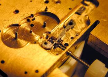
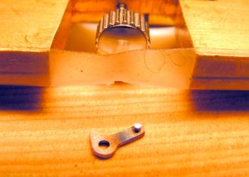
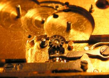
one. Below I am mounting the axle for the setting wheel on the clutch lever.
It is driven into a tapered hole from the top and after being reduced in
length on the lathe top and bottom, will be riveted from the underside.
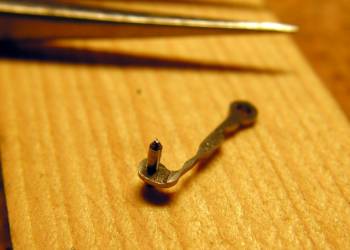
As you can see the neck that goes through
the sliding pinion is very slender. I do not know if it will hold up under
the forces coming from setting. I am not worried about the forces that will
be pulling the gear toward the minute wheel while turning the hands
counterclockwise. But when setting the time forward the forces on the axles
will be trying to push the intermediate setting gear away from the minute
wheel. The clutch lever will be flexing between the setting wheel pushing it
to the right and the setting lever pushing it to the left.
Now for the setting lever itself.
I wasn’t really expecting it, but the
movement is just right. But it came just as I had worried, the clutch lever
flexes too much. I can only set the time backwards. I could regulate fast,
but what will I do in the spring when summer time starts? It has dawned on me
that there are two more features of the keyless works that I have not taken
into account; a setting lever spring to be able to remove the stem from the
top of the movement and a detent spring to hold the setting level in either the
in or the out position. I decided to forget the detent spring as not
absolutely necessary. On the other hand I don’t want to play with a setting
lever screw that might unscrew itself and cause problems. I need to provide
for some kind of spring mounting of the setting lever. For some reason I had
provided for an access hole allowing to press the setting lever from the top
of the movement to be able to remove the stem, I just forgot the rest of the
mechanism. If I had thought of this while still on
the CAD drawing board I could have produced a nice solution including a
detent spring too. But as it is I will need a kludge. (In the mean time I
realize it would be no big problem to add a detent spring to my kludge, but
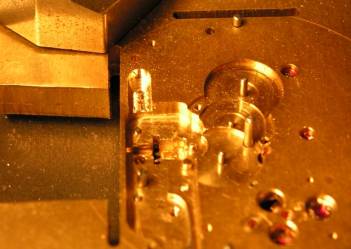
that is going to remain for the next movement.) So I carefully attack my pillar plate with
the milling machine again. The slot is at the right depth for the setting
lever spring to press on the ring around the pivot stud.
This spring is undercut from below and
flexes up and down. The undercut defines not only the flexing portion of the
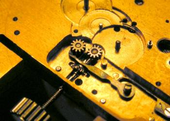
spring, but also the maximum movement of the setting lever. The next little problem to be resolved is
the flexing clutch lever. I am resigned to my fate to have the setting wheels
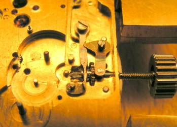
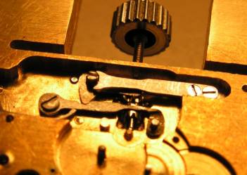
driven all the time. A new stud at the right position doesn’t move and has a
step to raise the gear to the right height.
The clutch lever in these pictures is one
that I broke while adding the stud at the end, but I don’t need the
prolongation anyway. Later on I took the longer clutch lever and filed off a
portion of the end holding the stud such that it just touched the fixed
setting wheel axle and gives a definite limit for the travel of the clutch
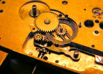
lever. Now time setting works fine. The biggest
remaining problem is that winding is very difficult, because of the
manhandled ratchet gear I think. So it is off to new horizons for me again,
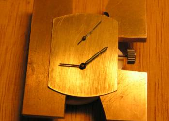
gear cutting. In the mean time the watch has gotten a
dial.
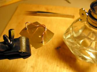
Soldering the dial feet and the movement
showing the time, with the hands I happened to have in the drawer. I hope you have enjoyed following this.
The next installment will be following soon. Don Copyright © 2005 Donald W. Corson |